When a component isn’t readily available in the Fritzing library, the most effective solution is to create a custom Fritzing part yourself. Initially, this may seem daunting, but once you become familiar with the process, you’ll find it quite rewarding. Learning to design a custom Fritzing part is like adding a new feather to your hat, as far as I can tell!
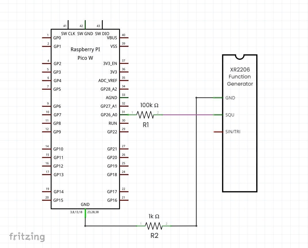
Backstory: While working on a schematic diagram to test the FunctionGeneratorKitwith XR2206 with Raspberry Pi Pico W, I couldn’t find it anywhere on the internet, including the Fritzing Library. So I captured a screenshot of the schematic design with the missing part. I then used a photo editor to draw the wire connections and overlaid the FunctionGeneratorKitwithXR2206 drawing to get the resulting image as shown below:-

This scenario made me think that creating any kind of circuit or schematic diagram with the FunctionGeneratorKitwith XR2206 would become less of a challenge if I could design a custom Frizting part on my own.
To begin, here are a few things you should know before designing a Custom Frizting Part for FunctionGeneratorKitwith XR2206:-
FunctionGeneratorKitwith XR2206 is a precise and affordable kit that produces square, sine, and triangle signals from 1Hz to 1MHz. Available pre-assembled or as a DIY project, it runs on a DC power supply. It includes jumpers and knobs for selecting the signal type/ frequency and for adjusting the amplitude /fine/coarse tuning.
Fritzing is a favourite EDA (Electronics Design Automation ) tool among hobbyists and educators as it simplifies electronics design with its user-friendly interface. It allows users to create custom parts using its Parts Editor, which is great for tailored projects. However, if you want the Fritzing team to create custom parts for you, it can be quite expensive, costing around €80 per hour.
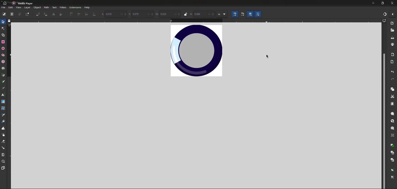
Inkscape is a versatile vector graphics editor known for creating scalable images, which is crucial for designing custom Fritzing parts. With its built-in XML Editor, it can transform images into code, guaranteeing fine detail and accuracy in customized components. Inkscape’s ability to handle SVG (Scalable Vector Graphics) means designs can be resized without losing quality, making it a popular choice for detailed and accurate projects.
Explore the FunctionGeneratorKitwith XR2206 in Action: Testing Scoppy Pico Smart Oscilloscope with 5 electronic circuits
Tips to design the custom Frizting part for FunctionGeneratorKitwith XR2206
When designing a new part in Fritzing, you need to customize three main sections: the Breadboard, Schematic, and PCB views. This process can seem overwhelming at first, but if you follow these pointers, you’ll be able to create a custom Fritzing part with ease.
I have compiled a few tips that helped me design the Fritzing part for the FunctionGeneratorKitwith XR2206 from scratch. Once you grasp the underlying thought process, you’ll quickly become proficient in creating custom Fritzing parts for your projects. Let’s delve into these tips for each section:-
1. Breadboard View

- Always design your virtual part according to Fritzing Standards, as stated in https://fritzing.org/fritzings-graphic-standards.
- The dimension of the virtual part must be the same as that of the real life component. To be more accurate, you can find its height and width from the datasheet:-
- To precisely match the colour of the virtual part to the real life component, you can pick its colour from the datasheet using online tools like Colorzilla.
- For adding SMD(Surface Mount Device)/Through-Hole components for the virtual part, here’s what you can do:-
- For example, grab a generic resistor in Fritzing and place it in the Breadboard View.
- Click on the placed generic resistor, from the Inpector Window→ select resistance as “330Ω,” tolerance as “±1%,” and bands as “5” from the respective dropdowns.
- Right click on modified generic resistor→Edit (new parts editor)→File→Export as Image→SVG
- Bring this image into Inskape, adjust its size, and place it over the virtual part. Proceed in the same way to add the other elements needed to produce the virtual part’s breadboard image.
- If you need only the top view of certain parts, modify them as shown in this video:-

- To make use of the official Fritzing recommended fonts (Droid or OCRA), here’s what you can do:-
- Download the fonts and templates folder from https://fritzing.org/learning/tutorials/creating-custom-parts/download-fonts-and-templates.
- Double click on each of the fonts in the extracted folder and install.
- Restart Inskape so that the fonts load.
- Fritzing uses a unique syntax to identify a breadboard drawing, select the whole object in Inkscape’s XML Editor, and change the group name to
<g:id="breadboard"> - Save the image “FunctionGeneratorKitwith XR2206.svg” in plain SVG format so that it can be uploaded in the Breadboard View of the Fritzing’s Parts Editor.
2. Schematic View

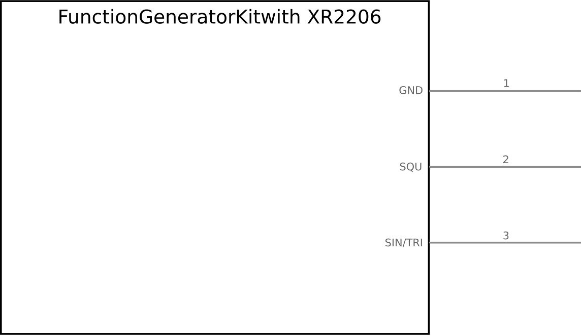
- Again, the rectangle that represents the schematic of the virtual part must be of the same dimension as the real life component. Fill it with white and give it a black outline of 0.012 inches.
- Make the pins of the virtual part Davys Grey coloured (#555555) with a thickness of 0.012 inches and length of 1 inch along with rounded tips.
- Keep the part name text black and the pin labels in Davys Grey (#555555) with the respective font sizes of 9 and 5.
- Fritzing uses a unique syntax to identify a schematic drawing, select the whole object in Inkscape’s XML Editor, and change the group name to
<g:id="schematic"> - Verify that the schematic snaps into place and the pins align with the grid precisely when you grab and move it.
- Save the image as “Schematic Drawing.svg” in plain SVG format so that it can be uploaded in the Schematic View of the Fritzing’s Parts Editor.
3. PCB View

- The Fritzing PCB View should only be used for designing the board prototype, not for the actual manufacturing of the PCB unless the part’s accurate dimensional footprint is measured from the datasheet.
- Fritzing uses a unique syntax to identify PCB drawings since they are made up of numerous layers. If not done correctly, you may receive an error while importing the PCB image in the Fritzing Parts Editor, as illustrated below:
ERROR: This version of the New Parts editor can not deal with separate coppero and copper 1 layers. So editing may produce an invalid PCB view image.
- Here’s what you can do to fix this error:-
- In Inksape’s XML Editor, group all copper pads under the name “copper 0,” then again group them under another group under “copper 1.”
- Place all the border outlines, texts, drill holes and logos in a separate group named “silkscreen.” Below is an illustration of this:-
<g:id="silkscreen">
<g:id="copper1">
   <g:id="copper0">
- Sometimes the copper pads don’t get scanned while selecting the graphic for connectors in Fritzing Parts Editor. Here’s what you can do to fix it:-
- Inksape’s XML Editor, rename the copper pad pins as shown below:-
<g:id="copper0">
  <circle id="connector0pin">
  <circle id="connector1pin">
  <circle id="connector2pin">
- Inksape’s XML Editor, rename the copper pad pins as shown below:-
- Save the image as “PCB Drawing.svg” in plain SVG format so that it can be uploaded in the PCB View of the Fritzing’s Parts Editor.
PROCEDURE
Create a custom Fritzing Part for FunctionGeneratorKitwith XR2206 by following these steps:-
- Launch Fritzing. Navigate to Core Parts→ICs→Generic IC. Grab the Generic IC and place it in the Breadboard View. Click on the placed Generic IC, from the Inpector Window→ select package as “SIP (Single Inline) [THT]” and the number of pins as “3” from the respective dropdowns. (Note: If the Inspector window is not enabled for some reason, then navigate to the Windows tab on the top and tick ✔Inspector.)
- Right click on the modified Generic IC→Edit (new parts editor). This action opens a window “Fritzing (New) Parts Editor.”
- Now, select Breadboard View→File→Load image for view→Browse for “FunctionGeneratorKitwith XR2206.svg”→Open. From the Connectors window that appears on the right:-
- pin 1 → select graphic→hover over the appropriate connector for pin 1 that gets highlighted in pink and click on it. Change its name and description to “GND.” Select terminal point→Center.
- pin 2 → select graphic→hover over the appropriate connector for pin 2 that gets highlighted in pink and click on it. Change its name and description to “SQU.” Select terminal point→Center.
- pin 3 → select graphic→hover over the appropriate connector for pin 3 that gets highlighted in pink and click on it. Change its name and description to “SIN/TRI.” Select terminal point→Center.
- Select Schematic View→File→ Load image for view→ Browse for “Schematic Drawing.svg”→Open. From the Connectors window that appears on the right:
- GND → select graphic→hover over the appropriate connector for this pin that gets highlighted in pink and click on it. Select terminal point→E.
- SQU → select graphic→hover over the appropriate connector for this pin that gets highlighted in pink and click on it. Select terminal point→E.
- SIN/TRI → select graphic→hover over the appropriate connector for this pin that gets highlighted in pink and click on it. Select terminal point→E.
- Select PCB View→File→Load image for view→Browse for “PCB Drawing.svg”→Open. From the Connectors window that appears on the right:
- GND → select graphic→hover over the appropriate connector for this pin that gets highlighted in pink and click on it. Select terminal point→Center.
- SQU → select graphic→hover over the appropriate connector for this pin that gets highlighted in pink and click on it. Select terminal point→Center.
- SIN/TRI → select graphic→hover over the appropriate connector for this pin that gets highlighted in pink and click on it. Select terminal point→Center.
- Select Icon View→File→Load image for view→Browse for “FunctionGeneratorKitwith XR2206.svg”→Open. (In this case, the icon is the same as the breadboard image.)
- Select Metadata View→ Fill in the details as follows:
- Title: FunctionGeneratorKitwith XR2206
- Author: Your Name
- Description: The XR2206 Function Generator is a precise and affordable kit that produces square, sine, and triangle signals from 1Hz to 1MHz. Available preassembled or as a DIY project, it runs on a DC power supply. It includes jumpers and knobs for selecting the signal type and frequency and for adjusting the amplitude and fine/coarse tuning.
- Label: Part
- URL: https://z100lifeline.swvagts.com/articles/XR2206FunctionGenManual.pdf
- Family: Function Generator
- Properties: pins:3; type:THT
- Tags: Function Generator; FunctionGeneratorKitwith XR2206; XR2206
- Select Connectors View→ Set all to:→✔ ♀→✔ Through-hole
- File→Save as new part→”FunctionGeneratorkitwith XR2206″→OK.
- Find your newly designed “FunctionGeneratorkitwith XR2206” under→Parts→Mine. Drag and drop the part in Breadboard View. Click on the hamburger icon ≣→Export part→Save as→ FunctionGeneratorkitwith XR2206.fzpz
- Finally, share your custom-made parts with the Fritzing community. View this page for further guidelines: https://fritzing.org/parts/
OUTPUT
Download the generated SVG images for each section along with the resulting Fritzing part here: FunctionGeneratorKitwith XR2206
This post was inspired by Fritzing Parts Fast by SidneyCritic ComedyHound
References:-
- https://www.instructables.com/Fritzing-Creating-Your-Own-Parts/
- https://hackaday.com/2017/01/06/creating-a-pcb-in-everything-creating-a-custom-part-in-fritzing/
For exclusive insights, tips and answers, please visit Wiztaqnia Forum.
- Can you inherit your data forever? - January 22, 2025
- The Future of Quantum Computing: What Will We Choose to Do? - January 15, 2025
- IoT based Indoor Air Quality ENS160 Monitor - November 20, 2024
