Let’s take a look at some of the terminologies in this DIY E-Project:
NodeMCU is an open source IoT platform. It includes firmware that runs on ESP8266 Wi-Fi Soc with ESP-12 module based hardware.
ESP8266 is a microcontroller with Wi-Fi capability.
If you take a look at all that NodeMCU has to offer, is best suited for anyone who is just getting started with hardware interfacing.
RFID(Radio Frequency Identification) system consists of two components:
-
- Tag: This does not run on any power supply. It is embedded with an antenna and a microchip containing its unique identification code.
- Transceiver Reader: It consists of a Radio Frequency module and a high frequency electromagnetic field generating antenna.
As soon as the tag is in close proximity to the reader, it electromagnetically powers up its microchip. The tag then responds by sending the unique identification code back to the reader in the form of radio signals.
The RF Module of the reader detects this signal and translates it into human-readable data and sends it to a microcontroller (here NodeMCU) via SPI communication.
E-COMPONENTS
Here is the list of all the required electronic components for this DIY E-Project along with respective purchase links:-
MODEL | E-COMPONENT | PURCHASE LINK |
 | NodeMCU ESP8266 | |
 | RFID Reader RC522 | |
 | MB20 Passive Buzzer | |
 | Jumper Wires | |
 | USB data cable |
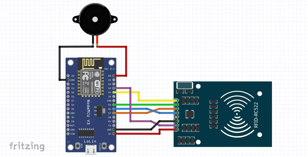
CIRCUIT DIAGRAM

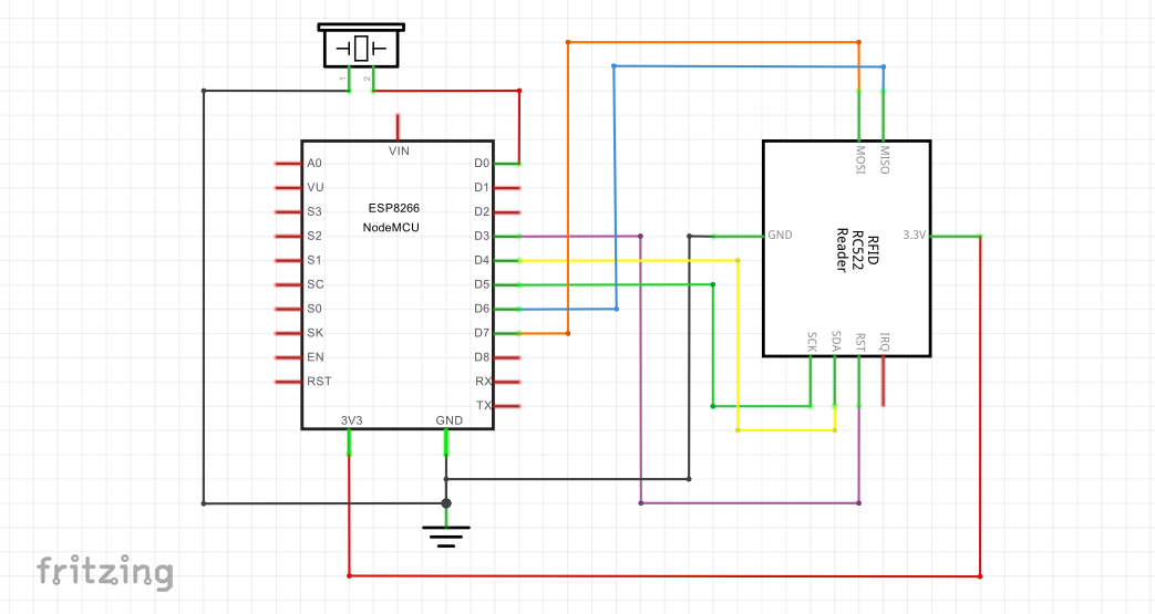
SCHEMATIC DIAGRAM
PROCEDURE
These are some of the step-by-step guidelines to be followed for this DIY E-Project:
-
- Install the latest Arduino IDE.
- Install ESP8266 library in Arduino IDE.
- Download MFRC522 library .ZIP file from the link https://github.com/miguelbalboa/rfid
- In Arduino IDE, go to Sketch->Include Library->Add .ZIP Library and install the MFRC522 library in Arduino IDE.
- Make hardware connections as per the above circuit and schematic diagrams.
- In Arduino IDE, go to Tools and select Board as NodeMCU 1.0 (ESP-12E Module) and COM port accordingly.
- Upload the “RFID UID identification sketch” from the programming section below to NodeMCU.
- Note the respective RFID UIDs of the white and blue tags respectively which are displayed on the serial monitor.
- Now edit the “Grant access to blue chain tag sketch” from the programming section below by writing the RFID UID of the blue chain tag in the place of “Blue Chain Tag RFID UID” in the if condition and execute.
- When the blue chain tag is in close proximity of the RFID reader interfaced with NodeMCU, the serial monitor displays the “Access granted” message and the BUILT-IN LED of NodeMCU is lit. If the white tag or any other RFID tag is in close proximity of the RFID reader, the “Access denied” message is displayed on the serial monitor and the passive buzzer is sounded for a certain time period.
PROGRAMMING
Sketch 1: RFID UID identification
/*
 * RFID UID identification sketch
 * Made by wiztaqnia.com
 *
 *  * Typical pin layout used:
 * -------------------------------------------------------------
 *                                  MFRC522      NodeMCU ESP8266
 *                                  Reader       Hardware SPI
 * Signal                           Pin          Interface Pin
 * -------------------------------------------------------------
 * RST(Reset)                       RST          D3
 * SPI SS(Slave Select)             SDA(SS)      D8
 * SPI MOSI(Master Out Slave In)    MOSI         D7
 * SPI MISO(Master In Slave Out)    MISO         D6
 * SPI SCK(Serial Clock)            SCK          D5
 */

#include <SPI.h>
#include <MFRC522.h>

 constexpr uint8_t RST_PIN = D3;  //Refer to the above pin layout
 constexpr uint8_t SS_PIN = D4;   //Refer to the above pin layout

MFRC522 rfid(SS_PIN, RST_PIN);    //Instance of the class
MFRC522::MIFARE_Key key;

String tag;

void setup() {
  Serial.begin(9600);  //Initialise UART Serial Communication with 9600 bits/s Baud Rate
  SPI.begin();         //Initialise SPI Bus
  rfid.PCD_Init();     //Initialise MFRC522
}

void loop() {
  if ( ! rfid.PICC_IsNewCardPresent())
  return;
  if (rfid.PICC_ReadCardSerial()) {
    for (int i = 0; i < 4; i++) {
      tag += rfid.uid.uidByte[i];
    }
    Serial.println(tag);
    tag = "";
    rfid.PICC_HaltA();
    rfid.PCD_StopCrypto1();
  }
}
Sketch 2: Grant access to blue chain tag
/*
 * Grant access to blue chain tag sketch
 * Made by wiztaqnia.com
 *
 * Typical pin layout used:
 * -------------------------------------------------------------
 *                                  MFRC522      NodeMCU ESP8266
 *                                  Reader       Hardware SPI
 * Signal                           Pin          Interface Pin
 * -------------------------------------------------------------
 * RST(Reset)                       RST          D3
 * SPI SS(Slave Select)             SDA(SS)      D8
 * SPI MOSI(Master Out Slave In)    MOSI         D7
 * SPI MISO(Master In Slave Out)    MISO         D6
 * SPI SCK(Serial Clock)            SCK           D5
 */
#include <SPI.h>
#include <MFRC522.h>

constexpr uint8_t RST_PIN = D3;   //Refer to the above pin layout
constexpr uint8_t SS_PIN = D4;    //Refer to the above pin layout

MFRC522 rfid(SS_PIN, RST_PIN);   //Instance of the class
MFRC522::MIFARE_Key key;

String tag;

void setup() {
  Serial.begin(9600);  //Initialise UART Serial Communication with 9600 bits/s Baud Rate
  SPI.begin();         //Initialise SPI Bus
  rfid.PCD_Init();     //Initialise MFRC522
  pinMode(LED_BUILTIN, OUTPUT);
  pinMode(D0, OUTPUT);
}

void loop() {
  if ( ! rfid.PICC_IsNewCardPresent())
  return;
  if (rfid.PICC_ReadCardSerial()){
    for (int i = 0; i < 4; i++) {
      tag += rfid.uid.uidByte[i];
    }
    Serial.println(tag);
    if (tag == "Blue Chain Tag RFID UID") {
      Serial.println("Blue Chain Tag Detected");
      Serial.println("Access Granted!");
      digitalWrite(LED_BUILTIN, LOW);
      delay(2000);
      digitalWrite(LED_BUILTIN, HIGH);
    } else {
      Serial.println("Unknown Tag Detected");
      Serial.println("Access Denied!");
      digitalWrite(D0, HIGH);
      delay(5000);
      digitalWrite(D0, LOW);
    }
    tag="";
    rfid.PICC_HaltA();
    rfid.PCD_StopCrypto1();
  }
}
This post was inspired by: https://miliohm.com/rc522-rfid-reader-with-nodemcu
For exclusive insights, tips and answers, please visit Wiztaqnia Forum.

Follow her socials: Linkedin | Quora | Instagram
- Can you inherit your data forever? - January 22, 2025
- The Future of Quantum Computing: What Will We Choose to Do? - January 15, 2025
- IoT based Indoor Air Quality ENS160 Monitor - November 20, 2024