When working on any electronic circuit, performing tests is a requirement. Generally, lab equipment such as an oscilloscope/signal generator is utilised in taking electronic signal readings and analysing the same. Presently with cutting-edge technical advancements, testing electronics no longer calls for bulky equipment only available at the laboratory. Since the form factor of electronics is getting compact, modern testing equipment has become portable and efficient!
Let’s take a look at some of the jargon you might come across in this DIY E-Project:-
- Raspberry Pi Pico/Pico W is a low cost, high performance microcontroller developed by Raspberry Pi Foundation. The Raspberry Pi Pico and Pico W are very similar in operation. Besides one major difference, the Raspberry Pi Pico W has the added feature of wireless connectivity.
- Oscilloscope is an electronic equipment that captures and displays electronic signal variation with time.
- Signal generator also known as a Function generator is an electronic equipment used to produce electronic signals catering for specific purposes or to generate different shapes of electronic signals.
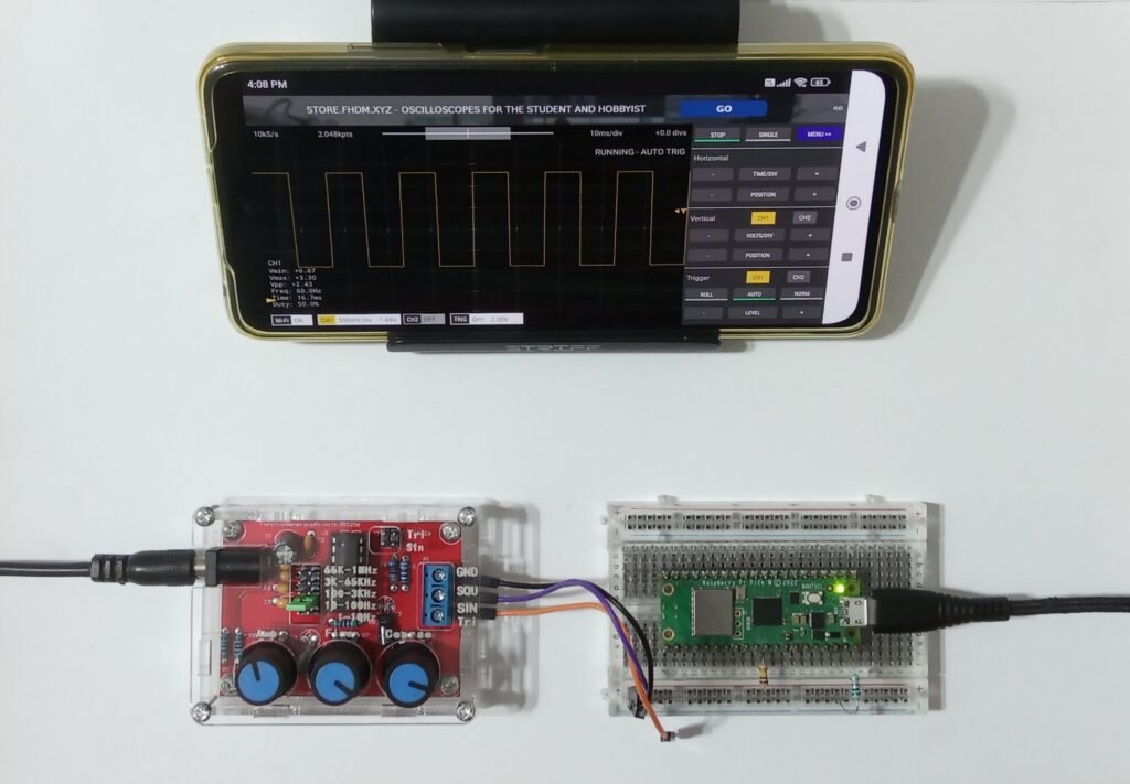
This is how the Scoppy Pico Smart Oscilloscope works. The Smartphone interacts with the Scoppy Pico loaded Raspberry Pi Pico/Pico W via the Scoppy App. The input signal changes when read from the GPIO26 Pin of the Raspberry Pi Pico/Pico W, which is displayed on CH1(Channel1) of the Smartphones’ Scoppy App. Nevertheless, the perk that comes with using Raspberry Pi Pico W is that it can wirelessly connect to the Smartphone via Scoppy Network.
After testing the Scoppy Pico Smart Oscilloscope with 5 electronic circuits let’s view the diagnostics in the Test Case section.
Explore the latest DIY E-Project: Colour changing Bluetooth WS2812B RGB ring light
E-COMPONENTS
These are all the electronic components which are required for this DIY E-Project and their purchase links:-
MODEL | E-COMPONENT | PURCHASE LINK |
 | Raspberry Pi Pico W | |
 | USB Female to Micro USB/USB Type C Connector | |
 | USB data cable | |
 | Android Mobile |
For creating the basic electronic circuits to test with the Scoppy Pi Pico Smartphone, here are the electronic components required along with their purchase links:-
E-COMPONENTS | PURCHASE LINK |
XR2206 Function Generator | |
10 uF 25V Electrolytic Capacitor | |
| |
Push Button Switch | |
5k Trim Pot | |
3mm LED | |
ESP8266 NodeMCU |
Disclaimer: I will earn a commission each time a visitor makes a purchase using my affiliate link.
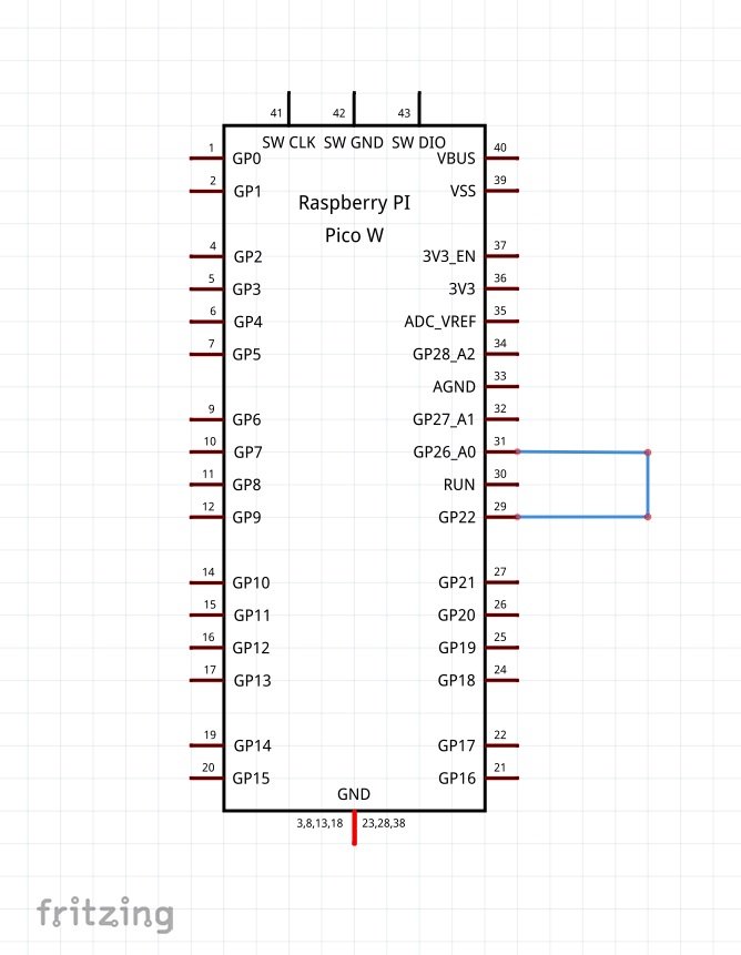
Pro Tip: The Raspberry Pi Pico/Pico W’s has its Pin names printed on the hind of its PCB. Consider referring to its PIN diagram while making connections for ease.
CIRCUIT DIAGRAM

PROCEDURE
Prerequisites for Scoppy Pico Smart Oscilloscope:-
- ≥Android version 6.0 (Marshmallow) or higher.
- USB OTG adapter/cable that is Smartphone compatible (not required when using the Pico W and connecting via Scoppy Network).
- Raspberry Pi Pico/Pico W model.
These are some of the step-by-step guidelines to be followed for DIY Scoppy Pico Smart Oscilloscope:-
- Check the prerequisite for the “Scoppy Pico Smart Oscilloscope” mentioned above.
- Download the Scoppy Pico firmware from oscilloscope.fhdm.xyz/wiki/Installation-&-Getting-Started based on your Raspberry Pi Pico/Pico W model.
- Press and hold the “BOOTSEL” button on Raspberry Pi Pico/Pico W and simultaneously connect it to your Laptop/PC via data cable. This will enable Raspberry Pi Pico/Pico W to appear as a USB mass storage device.
- Release BOOTSEL once the drive RPI-RP2 appears on your Laptop/PC. Paste the .uf2 firmware (download from step 1) to the Raspberry Pi Pico/Pico W.
- The built-in LED of Raspberry Pi Pico/Pico W starts blinking meaning that the Scoppy Pico firmware has been loaded successfully.
- Download the Scoppy App for your Smartphone from the Google Play Store.
- Connect your Smartphone to the Scoppy Pico loaded Raspberry Pi Pico W via USB or Scoppy Network:-
- Connecting Smartphone to Raspberry Pi Pico/Pico W via USB OTG :
- Make the connection as shown in the circuit diagram.
- Launch the Scoppy App→Allow Scoppy to Access Pico→Ok.
- Connecting Smartphone to Raspberry Pi Pico W via SCOPPY Network:
- Power up the Raspberry Pi Pico/Pico W from a Power Bank or Laptop/PC via data cable.
- Wait until the built-in LED starts blinking meaning that Pico W is ready.
- Go to the Wi-Fi settings on your Smartphone. Select the network name that begins with SCOPPY (for example, SCOPPY-A1234BC5678DE12A).
- Launch the Scoppy App. Tap the Connection→ Change connection type→ Wifi→ OK.
- Tap on RUN to establish the connection with the SCOPPY Network (Note:-The internet access is unavailable while your Smartphone/Tablet is connected to the SCOPPY Network).
- Connecting Smartphone to Raspberry Pi Pico/Pico W via USB OTG :
TEST CASES
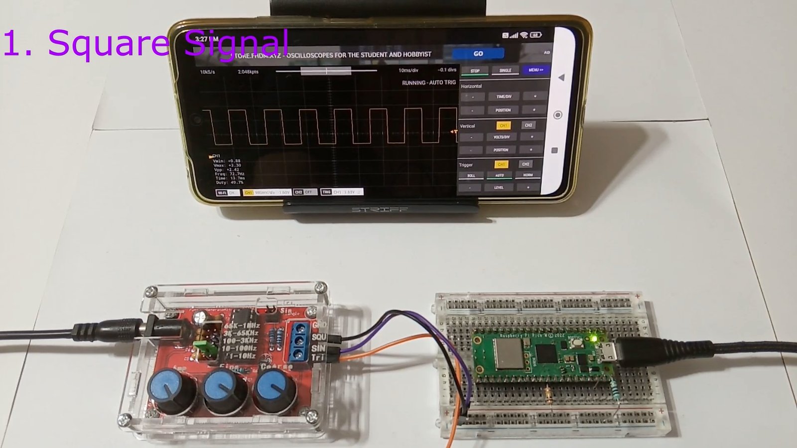
Test 1: Scoppy App’s demo signal generator
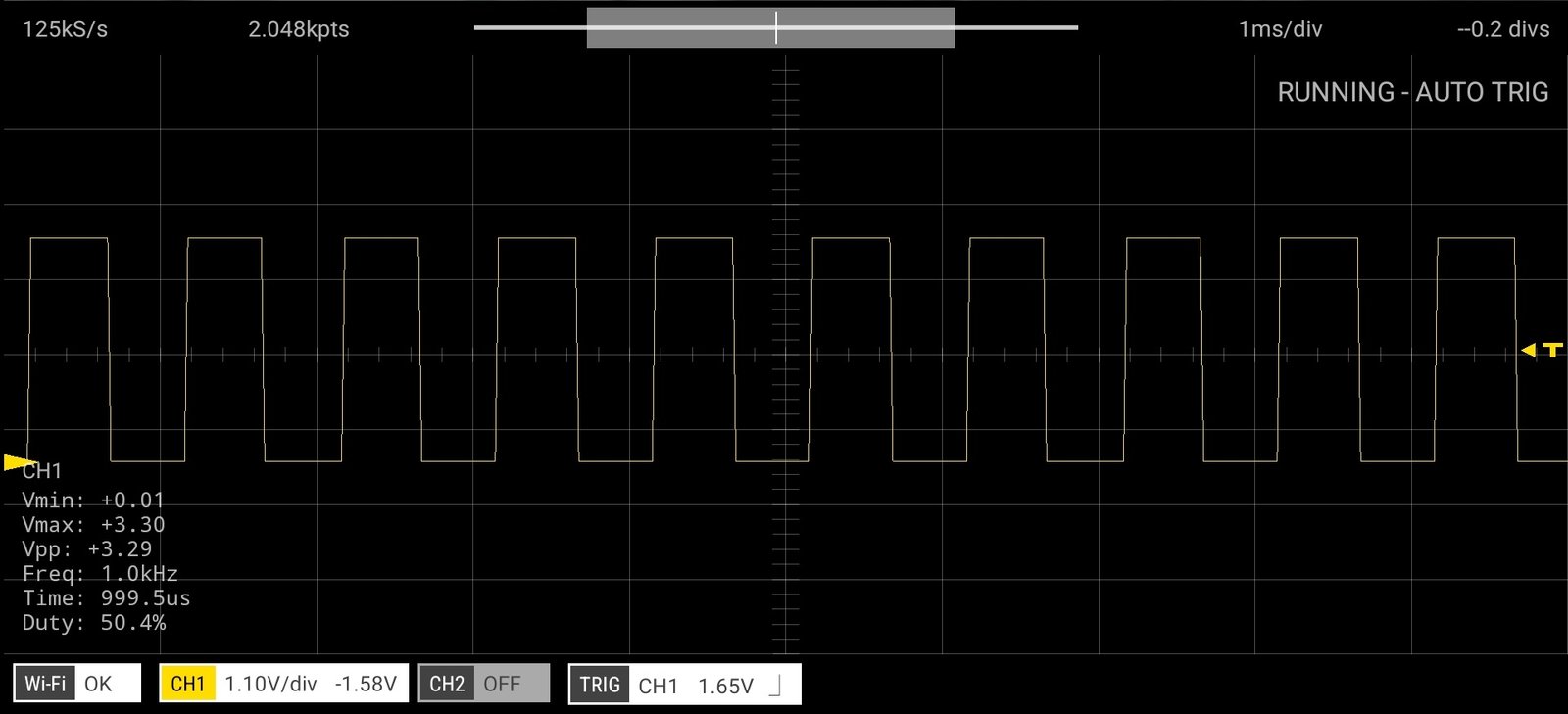
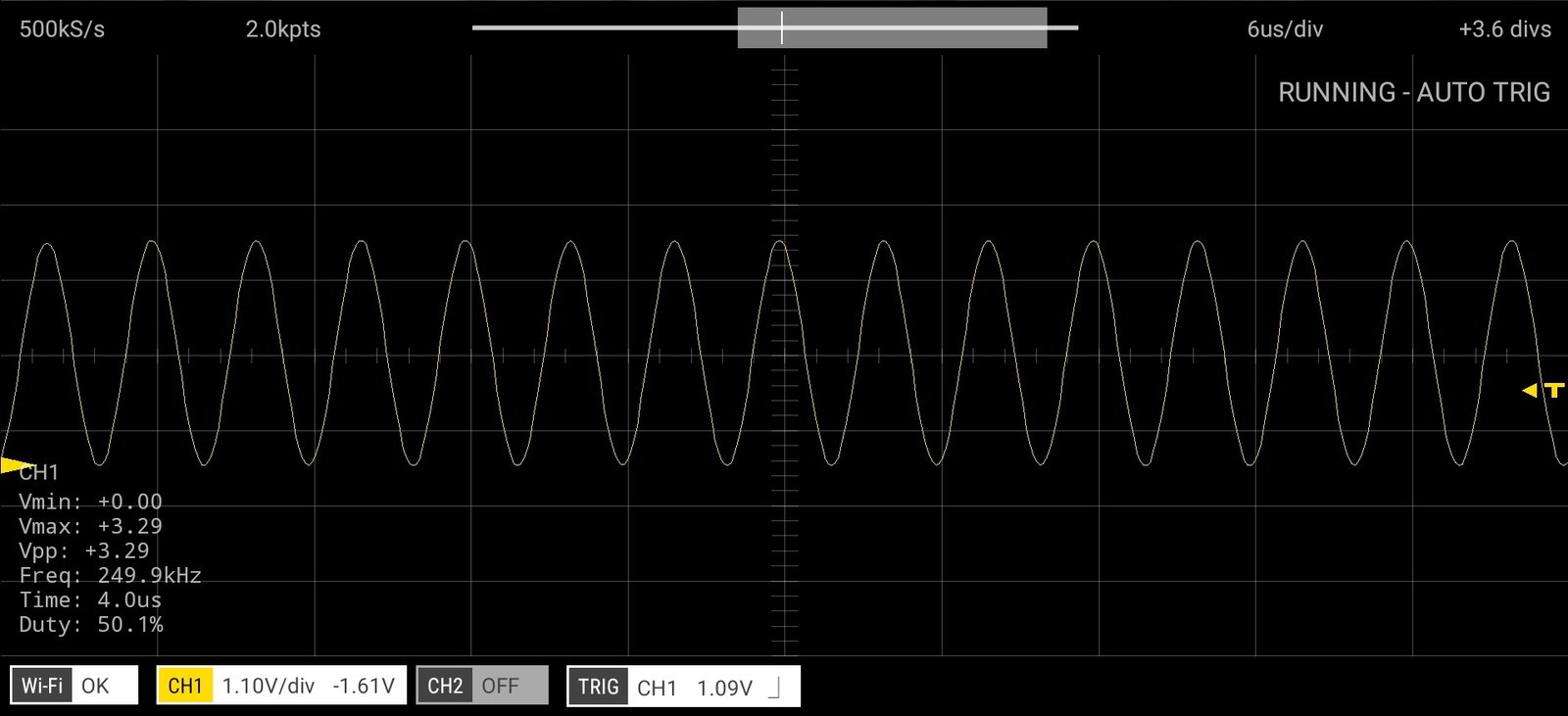
The Scoppy App has a demo signal generator feature that can generate a sine/square signal based on selection. To unlock this feature, make the connection shown in the above schematic diagram. From your Smartphone, launch the Scoppy App and connect it to Raspberry Pico/Pico W via USB OTG or SCOPPY Network. Navigate to→ Menu→ Signal Generator. Select the signal type as Sine or Square. You can also choose the signal frequency accordingly.
Below are the snapshots that depict the test results of Scoppy App’s demo signal generator for square and sine signal:-
Test 2: XR2206 Function Generator interfaced with Scoppy Pico Smart Oscilloscope
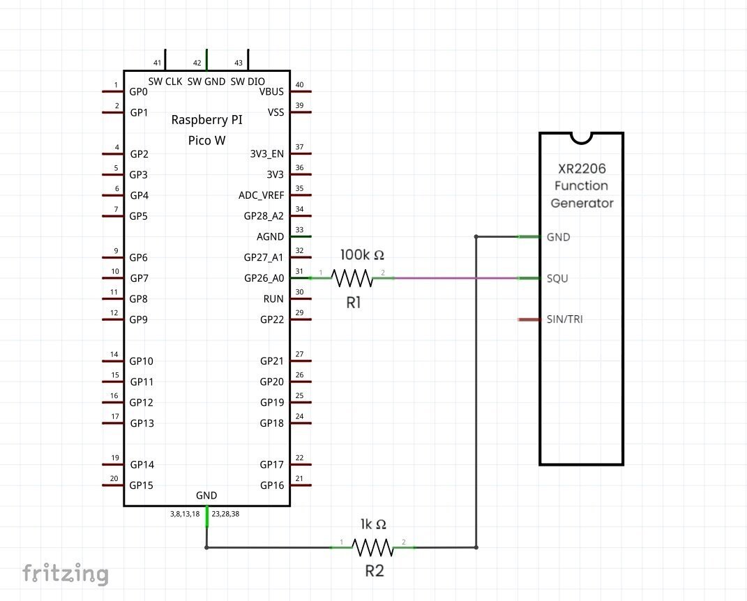
XR2206 Function Generator is a high-precision pocket-friendly signal generator kit that can generate square, sine and triangle signals of frequency range: 1Hz to 1MHz. This kit comes preassembled or you can DIY it by soldering all the components. It is powered by a DC power supply and has a few jumpers and knobs that can be used to select/tune the signal type as follows:-
- Signal Jumper: Set Sine or Triangle signal.
- Frequency Selection Jumper: Set the frequency range of the single:-
- 65k-1MHz
- 3k-65kHz
- 100-3kHz
- 10-100Hz
- 1-10Hz
- Amp Knob: Tune the amplitude of the signal.
- Fine Knob: Fine tune the frequency of the signal.
- Coarse Knob: Coarse tune the frequency of the signal.
To test the XR2206 Function Generator interfaced with Scoppy Pico Smart Oscilloscope make the connections shown in the above schematic diagram. R1 and R2 resistors prevent the Raspberry Pi Pico/Pico W from accidental high voltage damage that might incur from external signal sources.
Below is the video clip that depicts the test results of the XR2206 Function Generator interfaced with Scoppy Pico Smart Oscilloscope for square, sine and triangle signals:-
Test 3: Capacitor interfaced with Scoppy Pico Smart Oscilloscope
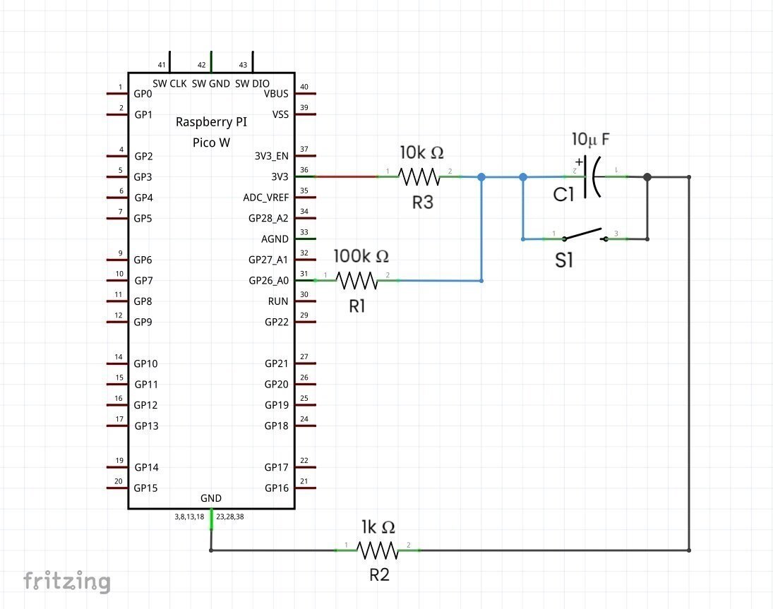
This is a simple circuit where the C1 capacitor is charged via an R3 resistor when the S1 button is pressed and gets discharged when the S1 button is released.
To test the Capacitor circuit interfaced with Scoppy Pico Smart Oscilloscope make the connections shown in the above schematic diagram. R1 and R2 resistors prevent the Raspberry Pi Pico/Pico W from accidental high voltage damage that might incur from external signal sources.
Below is the snapshot that depicts the test result of the Capacitor interfaced with the Scoppy Pico Smart Oscilloscope:-

Test 4: Potentiometer interfaced with Scoppy Pico Smart Oscilloscope
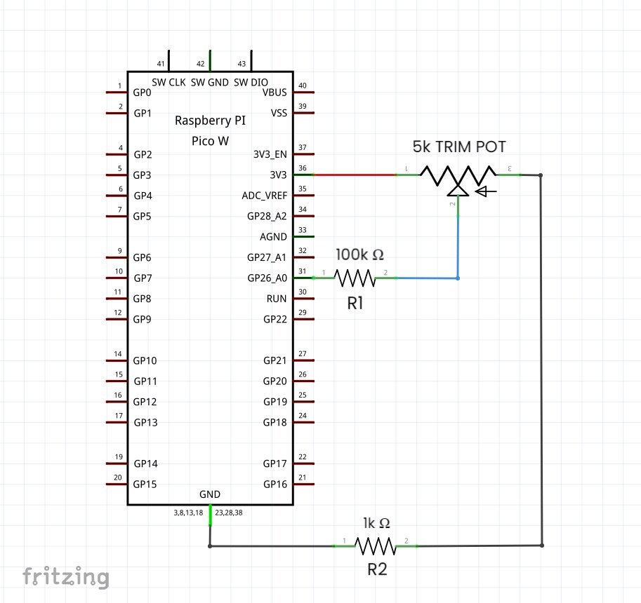
This is a simple circuit where the 5k Trim Pot potentiometer generates an arbitrary signal when varied from low to high value.
To test the potentiometer circuit interfaced with Scoppy Pico Smart Oscilloscope make the connections as shown in the above schematic diagram. R1 and R2 resistors prevent the Raspberry Pi Pico/Pico W from accidental high voltage damage that might incur from external signal sources.
Below is the snapshot that depicts the test result of the Potentiometer interfaced with the Scoppy Pico Smart Oscilloscope:-

Test 5.1: NodeMCU programmed to fade LED interfaced with Scoppy Pico Smart Oscilloscope
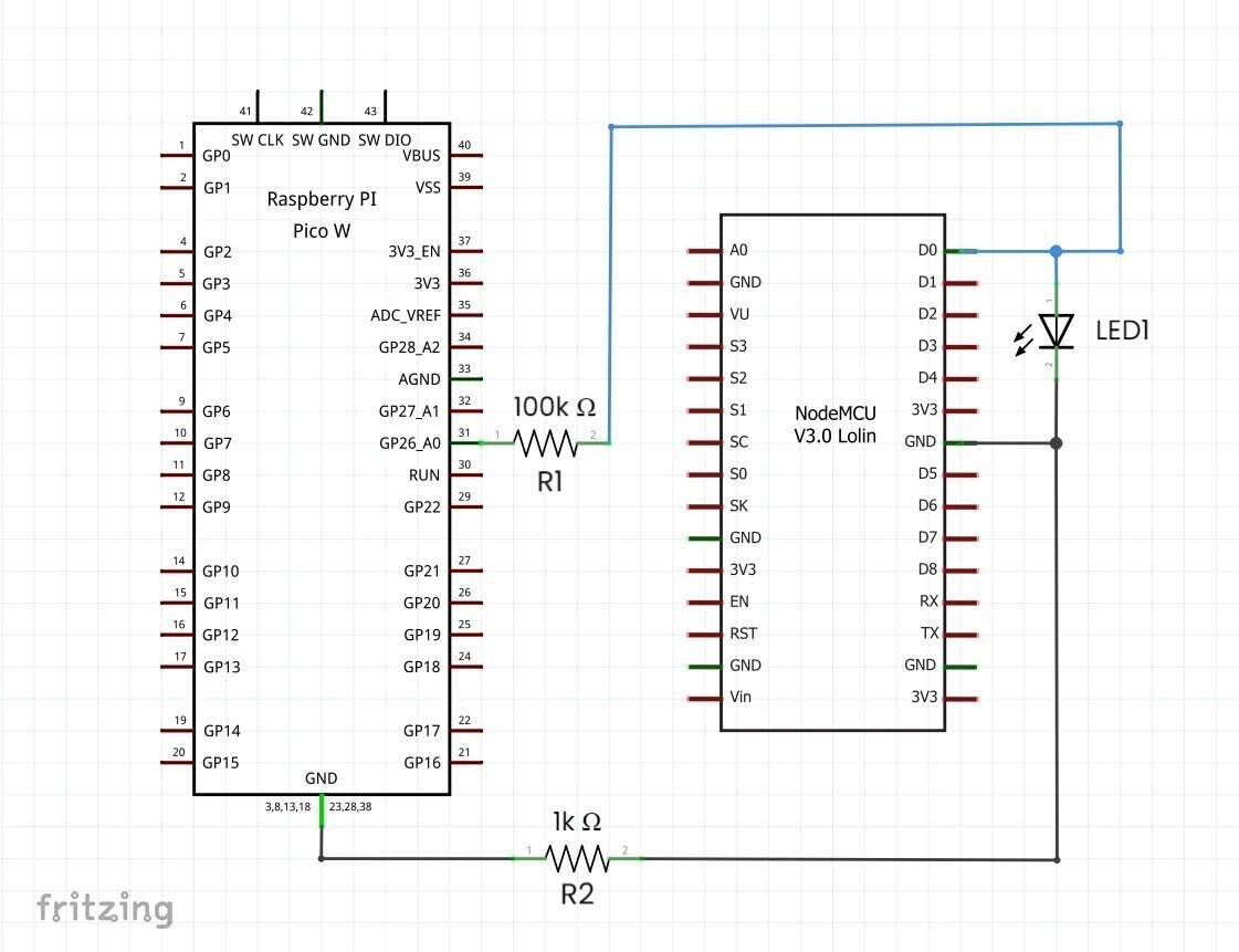
The NodeMCU is programmed to fade an LED where the brightness of the LED is gradually increased and then decreased by varying the digital PWM signal accordingly.
To test the NodeMCU programmed to fade an LED interfaced with Scoppy Pico Smart Oscilloscope and make the connections as shown in the above schematic diagram. R1 and R2 resistors prevent the Raspberry Pi Pico/Pico W from accidental high voltage damage that might incur from external signal sources. Upload the “NodeMCU programmed to fade LED” sketch shown below to NodeMCU.
Sketch 1: NodeMCU programmed to fade an LED
/*
 *NodeMCU programmed to fade an LED
 * Made by wiztaqnia.com
 * Modified date: 12/03/2024
 * Typical pin layout used:
 * -----------------------------------
 * Signal          NodeMCU      LED
 * -----------------------------------
 * Digital PWM        D0        +ve
 * GND(Ground)       GND        -ve
 */
int led = D0;
int fade = 250;
int bright = 5;

void setup() {
  pinMode(led, OUTPUT);
}

void loop() {
  analogWrite(led, fade);
  fade = fade + bright;
  if (fade == 0 || fade == 255) {
    bright = -bright;
  }
  delay(30);
}
Below is the screen recording that depicts the test result of the NodeMCU programmed to fade an LED interfaced with Scoppy Pico Smart Oscilloscope:-

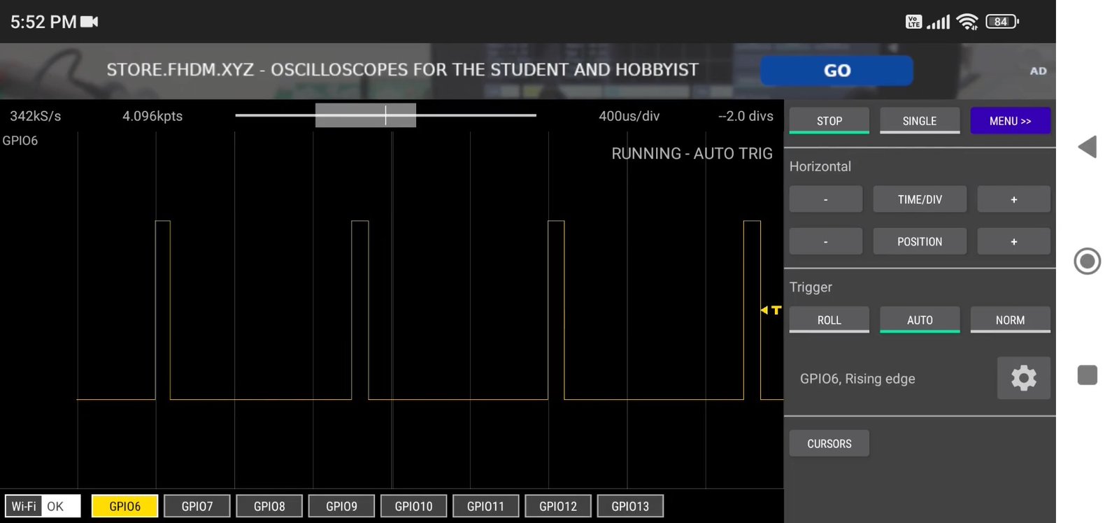
Test 5.2: NodeMCU programmed to fade LED diagnosed in Scoppy App’s Logic Analyser Mode
Apart from analog signals, digital signals can be diagnosed in Scoppy App’s Logic Analyser mode. To unlock this feature, connect PIN GPIO6 of Raspberry Pi Pico/Pico W to Pin D0 of NodeMCU and the rest is the same as shown in the above schematic diagram. From the Smartphone, launch the Scoppy App and connect it to Raspberry Pico/Pico W via USB OTG or SCOPPY Network. Navigate to→ Menu→ Mode→ Logic Analyzer.
Below is the screen recording that depicts the test result of the NodeMCU programmed to fade LED diagnosed in Scoppy App’s Logic Analyser Mode:-
This post was inspired by Raspberry Pi Pico Oscilloscope for your Smart Phone or Tablet, Scoppy Oscilloscope.
References:
- https://github.com/fhdm-dev/scoppy
- https://how2electronics.com/diy-smartphone-oscilloscope-using-raspberry-pi-pico/
- https://how2electronics.com/diy-function-generator-using-xr2206-kit-1hz-1mhz/
For exclusive insights, tips and answers, please visit Wiztaqnia Forum.

Follow her socials: Linkedin | Quora | Instagram
- Can you inherit your data forever? - January 22, 2025
- The Future of Quantum Computing: What Will We Choose to Do? - January 15, 2025
- IoT based Indoor Air Quality ENS160 Monitor - November 20, 2024